Metal Enclosed Electrical Bus, The Lifeline to the Transformer, What You Should Know and Why It’s Important to Your Bottom Line
BRIEF SUMMARY:
The purpose of this article is to educate power plant operators and maintenance personnel on the importance of metal enclosed electrical bus, an often-overlooked system critical component spanning from the generator to the main transformer, carrying the system’s full current. Metal enclosed bus is stand-alone, custom made for each plant, and non-redundant. When a failure occurs; the entire energy producing system shuts down until this critical component and its appendices are repaired or replaced.
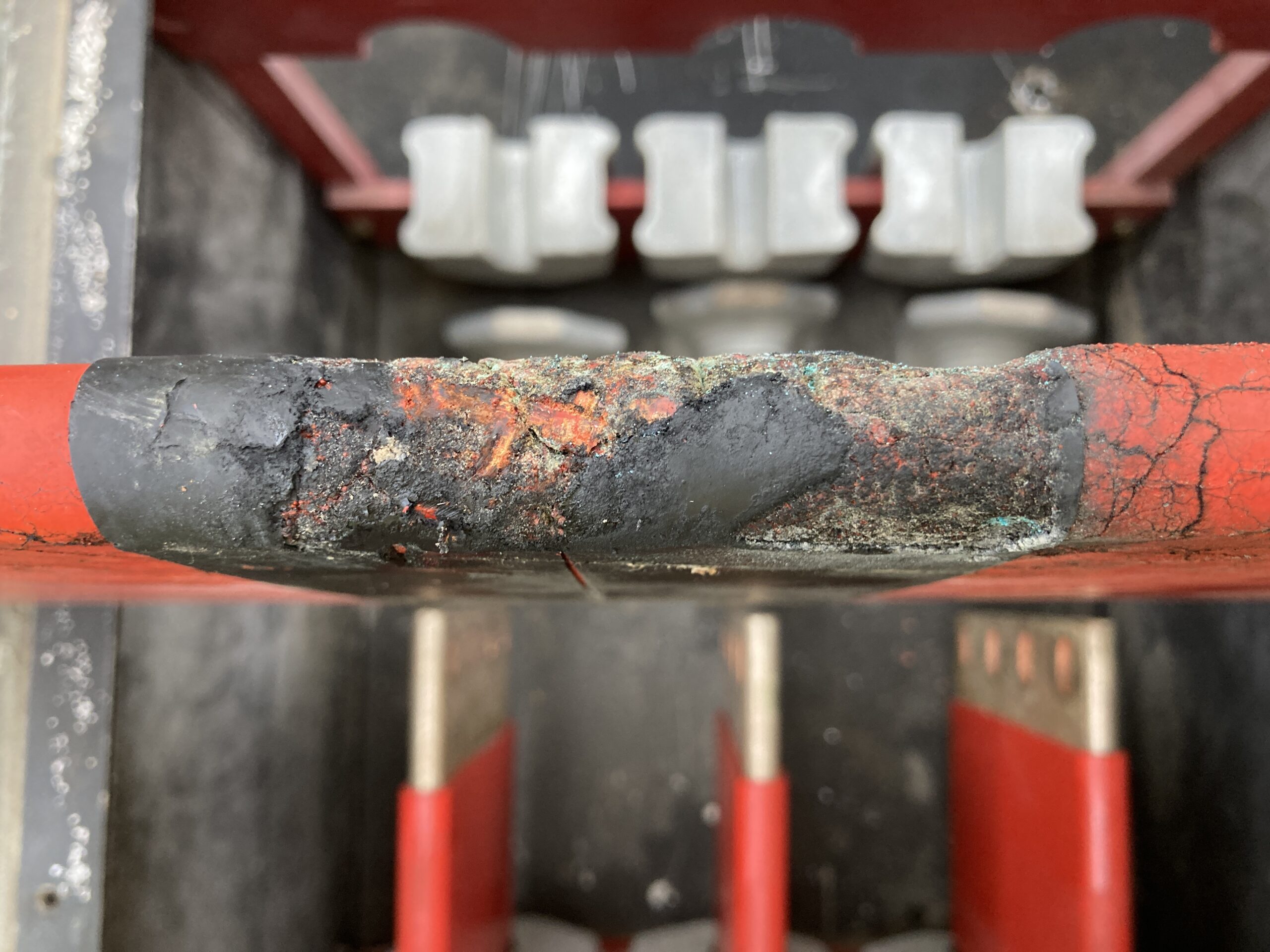
Most of us know what happens when a catastrophic event occurs at a transformer; power distribution comes to a grinding halt and plant personnel scramble into action to assess the damage and try to piece together the root cause in order to bring the system back to full operation as quickly as possible. However, what is almost always unexpected, is the logistics of replacing damaged electrical bus duct, an often-overlooked system critical component spanning from the generator to the main transformer, carrying the system’s full current. When a failure occurs, and the electrical bus duct is impacted, the entire energy producing system shuts down until the components and its appendices are repaired or replaced. The unplanned downtime often results in the revenue loss of hundreds of thousands of dollars while the plant isn’t generating power.
When a failure occurs, and the electrical bus duct is impacted, the entire energy producing system shuts down until the components and its appendices are repaired or replaced. The unplanned downtime often results in the revenue loss of hundreds of thousands of dollars while the plant isn’t generating power.
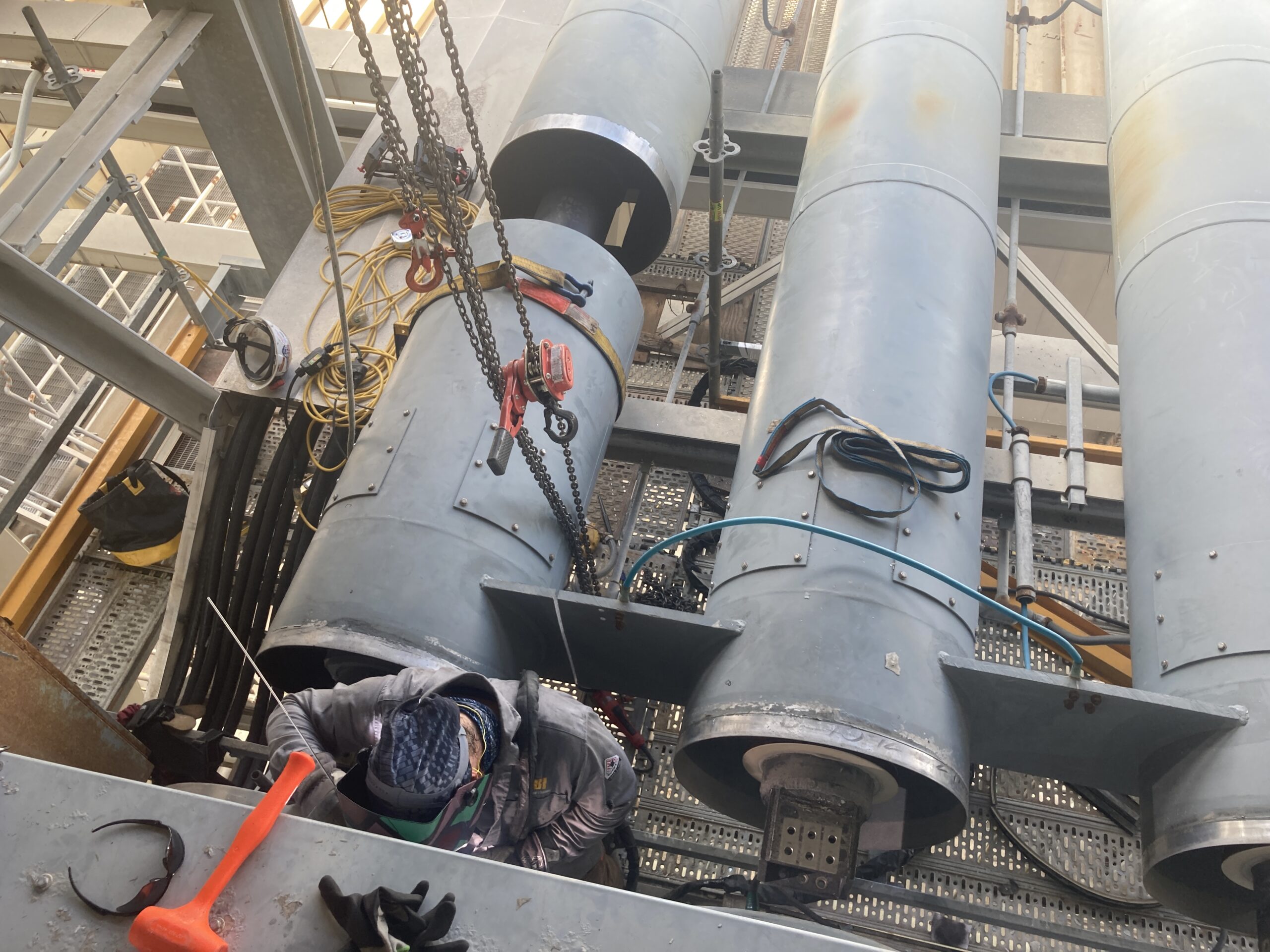
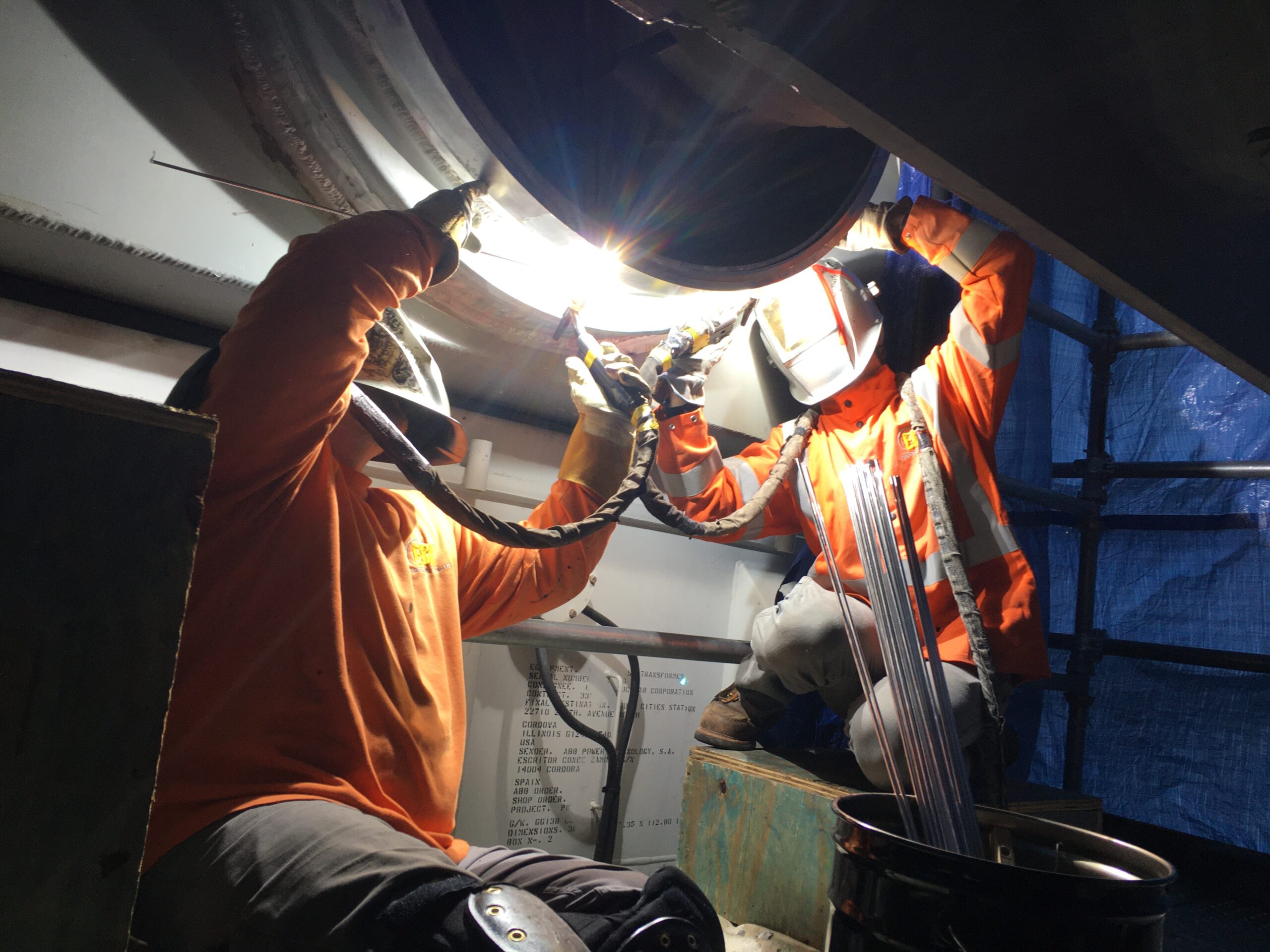
Metal enclosed electrical bus duct is custom designed and built specific to each plant’s specific electrical parameters. It has no moving parts. It also has no redundancy, despite it being a critical component in the overall generation system. Understanding the bus type connected to your transformer and the standard by which the bus is designed, is important. While there are many standards that cover different aspects of electrical bus duct, the current standard followed by all U.S. bus manufacturers is IEEE C37.23-2015. This standard supports four types of bus designs: Isolated Phase Bus (IPB), Segregated Phase Bus (Seg), Non-Segregated Phase Bus (Non-Seg), and Cable Bus. Most generators delivering current in the voltage range of 15kV to 38kV will have IPB installed. This doesn’t mean you won’t see systems connected with Cable Bus or Non-Seg Bus; it simply means IPB is the preferred bus to use. The main difference between IPB and the other bus types, is how the bus functions. Made primarily from aluminum, each phase conductor of IPB is housed inside its own enclosure with air space separating each phase. Assembled enclosure and conductor sections are welded together in the field except at termination to the major equipment where bolted flexible connectors are used. IPB design is also referred to as zero flux design since once energized, induced current from the conductor, flows through the housing, in the opposite direction from the phase current producing a magnetic field in the enclosure opposite to the conductor’s canceling each other out. Additionally, the forces created between conductors during a short circuit event will be significantly reduced. All other bus types produce very little induced current by the conductors, resulting in minimal magnetic fields in the enclosure. In short, the advantages of using continuously welded IPB are minimizing phase-to-phase faults, eliminating proximity effect for extra forces and heating, personnel protection (safe to the touch), and pliability. These factors make IPB the preferred bus design of choice for power generation.
Regardless of type, each bus electrical bus system is unique, and custom designed for each plant. While all bus manufactures must comply with the same IEEE design standards, each manufacture has their own specific method of constructing bus, which is unique to their company. However, what makes the bus a highly customized product, aside from meeting the plant’s specific electrical profile, is the bus layout from the generator to the main step-up transformer. The electrical bus system must weave through the plant and accommodate the changing elevations, twists, turns, connections to various cubicles, etc., all while maintaining the appropriate clearances and navigating through possible space constraints. When the bus meets at the transformer, the bus to transformer termination arrangement is housed in a customized aluminum compartment, also referred to as the “doghouse”. The doghouse contains the connections to the transformer bushings, all terminations typically using copper flexible connectors, rigid Copper adapter bars, and is bolted to the transformer face or top depending on the bushing orientation and in consideration of the required clearance to the high voltage side. As such, it is subsequently critical that the transformer termination configurations are designed appropriately to accommodate the fit up to both IPB and low voltage bushings of the transformer. For these reasons, when a failure occurs or transformer change-out is required, rarely is “like-for-like” replacement equipment readily available. Even when a “like-for-like” is planned, history and experience demonstrate that existing equipment conditions and environmental factors nearly always result in necessary bus modifications, fabrication of replacement components, transformer termination re-configuration, and proper assessment, planning and installation by an experienced bus duct service provider. All of these aspects are critical to minimize downtime and ensure safe and efficient return to service.
Even though the metal enclosed bus system is an integral component of the generation system, many engineers and plant maintenance personnel have limited awareness and experience of bus duct design, required maintenance procedures and frequencies, and best practices for transformer change-outs. This type of knowledge and expertise is unique and typically not covered in college curriculums, including engineering. This is one of the many reasons why the electrical bus system is often neglected and an afterthought when developing most contingency plans. When the unexpected occurs and the bus system is impacted, often, plant personnel don’t know who to call for repairs or where to find replacement parts. This causes further delays and ultimately, impacts the bottom line. Some plants are so unprepared they mistakenly hire contractors who are unqualified to handle bus duct maintenance and repairs, putting the entire system and those around it at further risk. Partnering with a proven and experienced bus duct contractor, such as Electrical Builders Inc., to develop a proactive emergency service and repair plan is critical to extend the life of the plant’s critical assets and is highly recommended as a best practice approach for leading power generation utilities.
Knowledge of electrical bus duct design and maintenance best practices is unique and not taught in any college curriculums, including engineering.